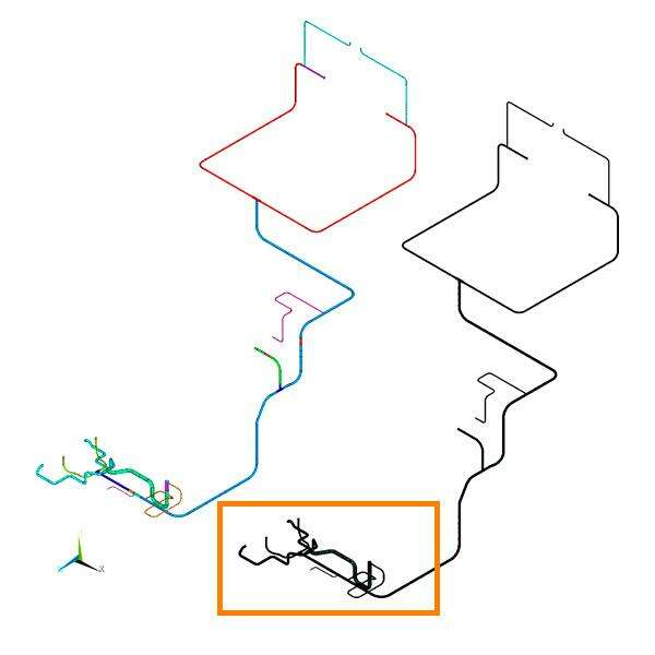
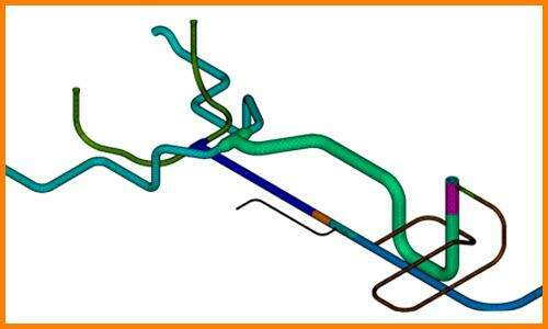
According to API579-1/ASME FFS-1 Section 10.5.2., the following analysis procedure can be used to evaluate a component operating in the creep range using the results from a stress analysis. The assessment is based on the stresses and strains at a point and through the wall thickness in the component, and the associated operating time and temperature.
1. Damage characterization. Evaluation of operating condition:
2. Material characterization:
3. Assessment Technique:
4. Assessment Procedures:
An inelastic analysis is used to evaluate the effect of creep, then a material model is required to compute the creep strains in the component as a fuction of stress, temperature, and accumulated creep strain (strain hardening model). If the computed stresses exceed the yield strength of the material at temperature plasticity should also be included in the material model.
The assesment procedure in this job provides a systematic approach for evaluating the creep damage for each operating cycle. The total creep damage is computed as the sum of the creep damages calculated for each cycle.
In addition to satisfying the previous damage criterion, if the stress components are based on an inelastic analysis that includes plasticity and creep, a limit on the total accumulated ineslastic strains should be set to a value that will not limit the operabiblity of the component. The suggested limit for the accummulated strains are proveded in Annex B1, paragraph B.3.3


Material model: creep strains are computed in the component as a function of stress, temperature, and accumulated creep strain (strain hardening model). If the computed stresses exceed the yield strength of the material at temperature plasticity should also be included in the material model.
The assessment procedure in this job provides a systematic approach for evaluating the creep damage for each operating cycle. The total creep damage is computed as the sum of the creep damages calculated for each cycle
If the stress components are based on an inelastic analysis that includes plasticity and creep, a limit on the total accumulated inelastic strains should be set to a value that will not limit the operability of the component.
In the preliminary evaluation of operational condition, operating temperatures (Tª=530ºC) were in creep temperature ranges according to table 4.1 of FFS.
For these reason, creep damaged could be present after FEM analysis.
Analysis considering material creep properties and plasticity did not converged at 20 hr of cycle, this may indicates that some pipe zones may present creep damage at operating and boundary condition considered on analysis.
Creep analysis is performed considering stresses from linear material behaviour FEM analysis and results indicates that creep damage due to operating and boundary conditions is much higher than the damage limit established in 0.8.
Creep damage= 1.8e14>> 0.8
Results of creep damage evaluation (considering stresses from linear analysis) indicates that creep damage occurs even very low operating hours.
This is in accordance with non-linear analysis results.
Moreover, according to screening criteria tables for level 1 assessment the maximum stresses must be lower than 250 MPa for 25 hrs and 115 for 250000 hrs, maximum stress results from linear analysis are higher than 1000 MPa, so it can be concluded that creep damage will occur at low cycle operation
CADE provides engineering, simulation and consulting services aimed to assess critical plant equipment, piping systems and structures when they are not performing as expected, a failure has occurred or their mechanical integrity and remaining life must be evaluated. To request more information about this type of services, please complete the following form:
For any further information , please complete the following form:
Albacete
Parque Científico y Tecnológico
Paseo de la Innovación 3, 02006 Albacete – España
Tel. +34 967 19 01 72
Av. Adeca, 55, 02007 Albacete
C/Raimundo Fernández Villaverde, 53 (Entreplanta) 28020. Madrid – España
Albacete
Parque Científico y Tecnológico
Paseo de la Innovación 3, 02006 Albacete – España
Tel. +34 967 19 01 72
C/Raimundo Fernández Villaverde, 53 (Entreplanta)
28020
Madrid – España